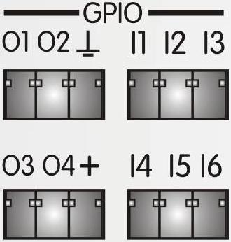
 The MAP-128/1216 processors include six logical input connections for general application (-General Purpose Input-) and four for output (-General Purpose Output-) thus allowing remote control to/from auxiliary equipment.
The GPIO connections use standard 3.5 mm pitch Phoenix™ connectors.
Both input and output connections share connections for positive (+) power and ground.
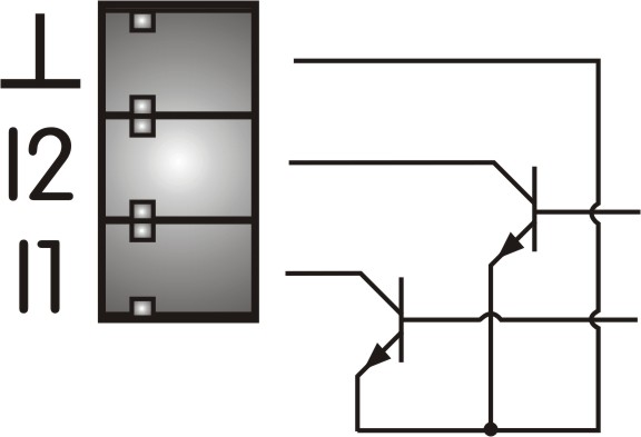
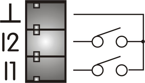
The inputs are logical, with an internal -pull-up- of 100 Kohm over 5 Volts and therefore the simplest form of external connection (triggering) is by using a simple push-button to ground or also connecting them to devices incorporating open collector outputs as shown in the accompanying diagrams.
 |  |
|---|---|
|
BUTTON TO GROUND |
OPEN COLLECTOR |
The GPIO inputs establish actions that have been previously defined under the 3cMAP control software such as:
Memory call -Preset Recall-, Input level, Inputs On/Off, Output level, Outputs On/Off, Routing and their levels, Voice message triggering as well as logical output triggering.
Since MAP processors do not incorporate controls on the front panel, the use of these logical connections through hidden controls or by triggering from other external devices linked to the audio control of the installation allows the necessary changes from day to day. A simple button allows to trigger the different presets predefined by the installer according to the client's needs. For more general control, the use of the REM-2 remote controller is recommended.
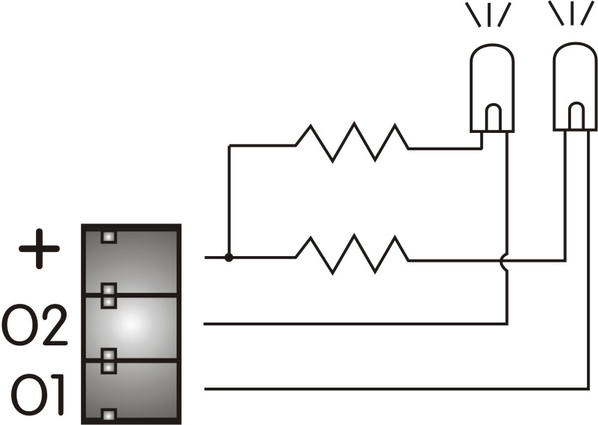
The outputs are open collector, so they accept control signals with different voltages outside the processor (50 Volts DC maximum). For small loads, the internal voltage of 5 volts DC (+ terminal) can be used to power external circuits with a maximum load of up to 500 mA in total. These outputs can be connected to LED type indicators and relays among others. If the load requires a voltage/current higher than that specified above, external sources can be used (50V/500mA max.).
 | 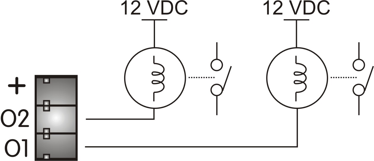 |
|---|---|
|
LED INDICATORS |
DC RELAY CONTROL |
The GPIO outputs will establish logic signal changes according to actions that have been previously defined under the 3cMAP control software such as:
Status of the input activation button On/OFF, Presence of an input signal, Peak level of an input signal, Status of the activation button of outputs On/Off, Presence of signal at the output, Peak level of an output, Event timer activated, Status of the USB and link indicators.
As an example, we could connect a led indicator to the O1 GPIO output to indicate when output number 8 peaks (peak level indication). Another application would consist of connecting a LOCAL OPEN indicator light through a relay to the O2 GPIO output and associated with the event timer with local time or to trigger a sound pressure limiter for certain time bands.