This is the main panel for the control and configuration of the input channels individually and in more detail.
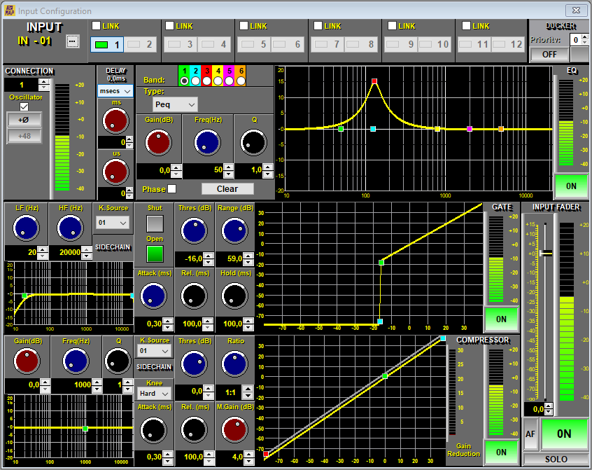
All available controls are listed below with a brief explanation (naming them from the top left corner of the panel down):
-
Channel Name: Select the "..." button (located in the upper left part of the panel) to customize the name of the selected channel (It will have a maximum of 8 characters).
-
Buttons 1 to 12: Channel selection keys. Pressing one of these keys will show all the parameters of the selected channel.
-
Ducker: Activate the ducker component and select the priority level. See configuration tab.
Pre-Amp Section
-
Connection: This text box makes a virtual connection or patching of the channel. By default, each channel is assigned the same pre-amp, but it is possible to patch to another pre-amp. Check 8. Block Diagram.
NOTE: When a channel is patched to a different pre-amp, the gain setting may be different from what we initially intended as it may have been adjusted from another channel. Note that the MAP has 12 preamps and therefore 12 preamp gain settings. In other words, the setting of a preview will be kept for all channels where it has been patched.
-
Oscillator: This switch activates the MAP local oscillator for that channel by disconnecting it from the pre-amp. The level setting and oscillator mode are modified in the tab Configuration → Oscillator.
-
Phase: Changes the relative phase of the signal.
-
+48V: Activate phantom power.
CAUTION: PHANTOM POWER. Be aware of the phantom power setting as standard devices such as CD players, etc. do not support this power and may be damaged. Watch the front panel indication +48V that is not activated. Phantom power is used for professional microphones and other audio accessories such as injection boxes.
-
Gain: Adjusts the pre-amp gain from 0 to +54 dB in 1 dB steps. The preamplifier design allows the use of mic and line signals in the same connector and without the need for an attenuator or PAD for most signals:
-
PRO signals LINE: For best result, set the gain to 0 dB as the initial setting. This 0 dB setting allows the maximum input capacity of the preamplifier of up to +20 dBu without clipping.
NOTE: For best noise results, set the gain to +1 dB. The maximum input signal is reduced to +13 dBu.
-
CONSUMER signals LINE: Adjust the gain to any level. The typical setting is +10 dB.
-
MIC with dynamic microphones: Adjust to the required level. Typical setting is +25 to +40 dB.
-
MIC with condenser microphones: Adjust to required level. The typical setting is +10 to +25 dB.
NOTE: Pro signal Lines are normally distinguished by the use of XLR connectors and balanced signals. Nominal levels are usually 0 or +4 dBu. For signals greater than +20 dBu, an external 10-20 dB balanced attenuator is required. consumer line signals are typically found in players and devices with din/cinch connectors and nominal levels are around -10 dBu. When connecting headphone outputs from computers, tablets, etc., adjust the gain as PRO LINE signals to avoid distortion since very high signal levels are handled.
-
-
Bargraph: Level indicator. Indicates the level in dBu from -40 to +20 dBu in 2 dB steps. The bar changes its hue according to the level, going from green to deep red. The indication incorporates a peak level hold led with a long time constant.
-
Delay: This component introduces a delay of the input signal that is very useful for various applications. The setting range is from 0 (no delay, default value) to 990 ms maximum. The delay can be entered as time or as distance traveled in meters or feet at a given temperature. When the distance is entered the user can define the current temperature and the MAP will adjust the necessary time delay automatically.
-
6-Band EQ: The EQ section consists of a six-band parametric equalizer. Each band can be defined as:
-
Peq: Parametric filter with selectable gain (dB), Frequency (Hz) and bandwidth (Q factor).
-
Low Sh/High Sh:Butterworth type bass or treble side filters.
-
Notch: Notch filter. Allows you to cancel a very narrow band without its being almost noticeable.
-
-
Equalization Graph: It is the result or EQ graph of the filters, delays, etc. that have been configured. This can be molded with the mouse or edited numerically:
-
Level/Frequency: Can be edited by sliding up or down to adjust dB and moving from left to right to set Frequency (Hz).
-
Bandwidth (Q): It can be varied by means of the mouse wheel positioned over the band identifier.
-
Band Button: Allows you to select a Band.
-
Phase Button: Allows you to indicate the phase graph.
-
Clear Button : Allows you to reset the EQ to its default settings.
NOTE: EQ parameters can be saved or copied to make it easier to set up multiple channels that require the same or similar EQ setting. Use the right mouse button for these options.
-
-
ON/OFF: EQ on/off or bypass key. Disconnect the EQ leaving the section semi-transparent to allow quick activation.
Noise Gate Section
-
Gate: A noise gate is a process similar to an expander but with a more abrupt and adjustable level change. Signals entering the gate detector less than the set threshold will keep the gate closed (-shut-) so the output signal will be muted (or attenuated). When the signal is somewhat higher and exceeds the threshold, the gate opens (-open-) so the signal will pass unchanged.
-
The noise gate level detectors include a -side chain- filter with variable bandwidth and trigger channel selection -key source selection-. The audio signal is not altered or processed in this filter. Check 8. Block Diagram.
-
SIDE CHAIN: The gate detector takes the signal from its same channel or can be patched from another channel to allow conditioned triggers (by default from the same channel). Thanks to this feature it is possible to open or close several channels from the same channel. A classic example is found when processing a stereo signal, the gates of both channels must be triggered in a synchronous way from one of the channels.
The -side chain- filter will help to limit the action of the noise gate when faced with signals of a certain characteristic or frequency pattern. This means that a low frequency present in a signal will not open the door of a presenter whose -side chain- has been filtered for a speech pattern (300 to 3KHz).
-
LF(Hz): Defines the lowest frequency that enters the noise gate detector (Minimum Frequency).
-
HF(Hz): Defines the highest frequency that enters the noise gate detector (Maximum Frequency).
-
K.SOURCE: Channel patching for the -side chain-. Defines the channel selected for triggering. See diagram.
-
CLOSE/OPEN LEDS: These LEDs indicate the activity (closed or open) of the noise gate.
-
THRESHOLD: Threshold of the noise gate. Defines the threshold point or reference level for triggering.
-
RANGE: It is defined as the residual attenuation of the signal when the noise gate is closed. Small ranges make the opening or closing action less abrupt and if they work they are the most advisable.
-
ON/OFF: Turning the noise gate on or off (-by-pass key-). Disconnect the noise gate leaving the section semi-transparent to allow quick activation.
The range and threshold can be adjusted graphically from the curve. The highest point defines the threshold point while the range is established by the distance from the threshold to the lowest point of the curve. Both points are adjusted by sliding the mouse up or down.
-
Compressor/Expander Section
-
Compressor: The dynamic section of the MAP includes a compressor/expander on each input. By changing the input output ratios the dynamics processor will go from compressor to expander. In the intermediate zone, with a 1:1 ratio the processor will be without effect. The parameters that define the dynamic behavior are:
-
COMPRESSOR: Adjustable compression ratio from 1:1 (no effect) to oo:1 (limiter).
-
EXPANDER: Expansion ratio from 1:1 (no effect) to 1:7 (very pronounced effect, noise gate).
-
COMPRESSOR/EXPANDER BAND: The inclusion of a parametric equalization section EQ creates a spectral correction so that the dynamic effect of compression or expansion is more pronounced at certain frequencies. This effect (-de-esser-) is widely used to correct excessive bias in some phrases and for many other applications.
-
K.SOURCE: Channel patching for the side-chain. Defines the channel selected for triggering. See diagram.
-
THRESHOLD: Compressor/expander threshold. Defines the threshold point or reference level for triggering.
-
KNEE: In compressor mode there is the possibility of choosing an abrupt (-hard-) or smooth (-soft-) transition. This setting allows a more natural transition of the compression effect just when the signal is close to the threshold or effect start level.
-
RATIO: Defines the ratio of change of the output signal to the input signal either in compressor mode or in expander mode. A ratio of 1:1 does not produce changes. For a threshold setting (-THRES-) to 0 dBu, a ratio of 2:1 (-COMPRESSOR-) reduces a 10 dBu input signal to 5 dBu and on the other hand, a ratio setting of 1:2 (-EXPANDER-) translates a 5 dBu input signal to 10 dBu.
-
ATTACK AND RELEASE: The time constants of the dynamics processor can be adjusted here: attack or time it takes to react as well as recovery (-release-) or continuation of the effect once the signal to treat has disappeared.
-
M.GAIN: Make-up Gain. Este mando realiza un ajuste de nivel ya sea de ganancia o atenuación posterior al procesador de dinámica para compensar los cambios realizados y poder dejar el nivel más adecuado de salida.
NOTE: It is advisable to adjust this knob with caution since it is post-compressor.
The ratio and threshold can be adjusted graphically from the transfer curve. The highest point defines the slope of the curve, so shifting defines the ratio and the lowest point defines the threshold. Both points move up or down to the new values.
An additional bar indicates the Gain Reduction experienced by the signal. When the processing is compressor type the bar is shown in -red- and will change to -yellow- when it is processed in expander mode (-Gain Expansion-).
-
Input Fader Section
-
Input Fader : Represented with an extra detailed level indicator. These elements can be defined with certain movements of the Fader:
-
DOUBLE CLICK: Sets the Fader value to 0 dB quickly.
-
SELECTION: By clicking on the Fader you will select it and it will change from YELLOW to BLUE. From now on you can use the mouse wheel to adjust the level of the selected Fader in 0.5 dB steps.
-
NUMERICAL ADJUSTMENT: You will be able to adjust the Fader value more precisely using the text box located in the position immediately below the level bar (-level bargraph-) of the Fader . This modification can be done using the +/- arrows, the numeric keyboard and the mouse wheel.
-
-
AF: With this key we will activate or deactivate the Anti-Feedback effect in the selected channel.
-
ON-OFF: Channel ON or MUTE switch. It is activated and displayed indistinctly from both input panels Inputs and Input Configuration.
-
SOLO: This button causes a -solo- of the selected input, mute (turning off) the rest of the inputs. This function is used to isolate an input from the rest of the system so that the system can be analyzed in a check-up procedure. This key should only be used for testing, it will NEVER be used in daily processing. When the MAP is used as a microphone mixer, this key is very useful to momentarily isolate a channel such as a presenter, canceling out the rest of the sound sources. Pressing this button again will return the system to its previous state without the need to reposition any faders.
NOTA: Use this button with caution.