This section provides an overview of the 12 inputs with their most important parameters at a glance. For a more precise setting go to the Input Configutation Panel.
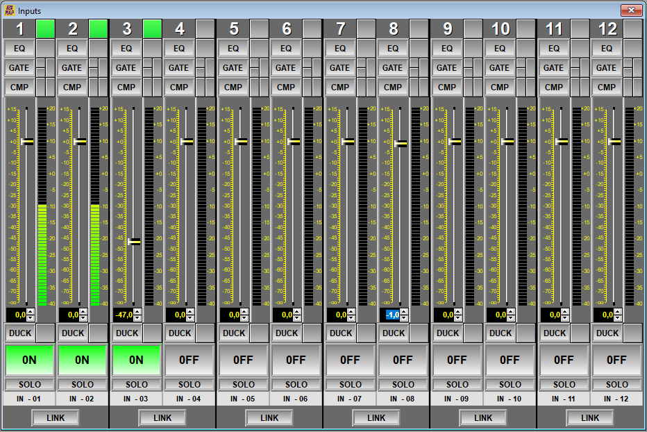
In this panel we can see that we have the following elements for each channel:
-
EQ: Represented with a -by-pass- key and a level bar (-level bargraph-).
-
GATE: Noise Gate. Represented with a -by-pass- key, door open (GREEN) or closed (RED) LEDs and a level bar (-level bargraph-).
-
CMP: Compressor-Expander. Represented with a -by-pass- key, a gain reduction or expansion indication LED and level indicators (-level bargraph-).
-
FADER: Represented with an extra detailed level indicator. This elements can define certain movements of the Fader:
-
DOUBLE CLICK: Sets the Fader value to 0 dB quickly.
-
SELECTION: When you click on the Fader you will select it and it will change from YELLOW to BLUE. From now on you can use the mouse wheel to adjust the level of the selected Fader in 0.5 dB steps.
-
NUMERICAL ADJUSTMENT: You will be able to adjust the Fader value more precisely using the text box located in the position immediately below the level bar (-level bargraph-) of the Fader . This modification can be done using the +/- arrows, the numeric keyboard and the mouse wheel.
-
-
DUCK: Ducker activation and indicator LED. Double clicking on the activity LED will open the Ducker parameter window.
NOTE: For more information consult the section 7.2.4.1. Input Ducker.
-
ON/OFF: On or Off button. This is the main switch, also known as -MUTE- of the channel.
-
SOLO: This button causes a solo of the channel, mute (turning off) the rest of the channels. This function is used to isolate the channel from the rest of the inputs and thus be able to analyze the system in a check procedure. This key should only be used for testing, it will NEVER be used in daily processing. When using the MAP as a microphone mixer, this key is very useful for momentarily isolating a channel such as a presenter, canceling out the rest of the sound sources. Pressing this button again will return the system to its previous state without the need to reposition any faders.
NOTE: Use this button with caution.
-
IN-01: In this button the name assigned to said entry will appear. Pressing this button will access the Input Configuration Panel of the input in question.
-
LINK: This switch makes the two adjacent channels operate as a single channel in terms of their settings with the exception of the -preamp- gain which can be adjusted individually. When channel pairing or -link- is performed, the EQ, gate, compressor and fader settings of the even channel will be lost and replaced by the parameters of the odd channel. On the other hand, when returning to individual mode or returning from LINK mode, the parameters will not be modified, that is, the parameters of the even channel will remain the same as those of the odd channel and if you want them to be different you will have to modify them manually.