![]() When the installation falls short in terms of the number of inputs or outputs, there is the possibility of expanding by connecting another linked processor. MAP processors incorporate a unit interconnection connector or -LINK- that allows us a combined processing of the signals of the two processors.
When the installation falls short in terms of the number of inputs or outputs, there is the possibility of expanding by connecting another linked processor. MAP processors incorporate a unit interconnection connector or -LINK- that allows us a combined processing of the signals of the two processors.
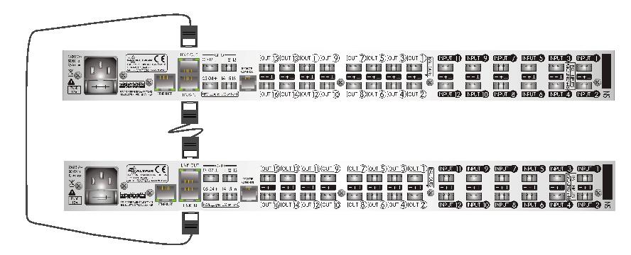
The chained or link is carried out by means of two connectors of the RJ45 type using 2 connecting cables used for Ethernet networks. These patch cords will be made up of 4 pairs of twisted cable Cat5 type.
Make sure the wiring is pin-to-pin on all 8 wires by checking the color code at each end. The hoses should be the shortest size available. A length of 0.5 to 1 meter is very common. The indicators on the front will show the link connection. The indicators on the rear link connectors are not arranged to indicate the status of this connection or the signal present.
As indicated in the figure, you must wire the link out output of a device A to the link in input of device B and in the other direction, wire the link out output of device B to the link in input of device A.
 |
|---|
|
COMBINATION |
INPUTS |
OUTPUTS |
|---|---|---|
|
MAP128 + MAP128 |
24 |
16 |
|
MAP128 + MAP1216 |
24 |
24 |
|
MAP1216 + MAP1216 |
24 |
32 |
3cMAP Control
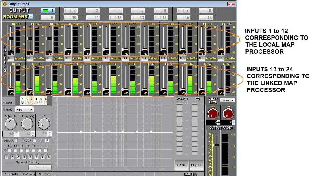
The 3cMAP software will detect the presence of the other device and will adapt in terms of the number of inputs to be processed in its Matrix section, OUTPUT CONFIGURATION program window. See figure below.
The input and output sections will remain unchanged since their number does not change.
As we now have two devices, we must open a 3cMAP program for each device from the same PC. Each program will be responsible for the settings of each device both in its own management and in the treatment of the memories that will be made independently for each device from its linked program.
Remote Control REM-2
The handling and properties of the remote controls will also be linked to each program and each device separately. In this sense, installations with a double processor must be equipped with double remote wiring, one wiring for each device. The association of functions or actions of the remotes on both devices simultaneously is not contemplated in the design of MAP processors and therefore each remote will only have control access over the physical inputs and outputs of its associated device.
GPIO Control
As in the previous section, the management and properties of remote control by logic inputs/outputs or GPIO will be linked to each program and each device separately and the installation must be carried out under these specifications. In this sense, duplicate controls could be implemented, one per device, by using, for example, pushbuttons or double-circuit relays (2+2 pins) to simultaneously trigger a preset or an action of each device so that we obtain a global action.