→ Configuration → Gpios
NOTE: For detailed information on the logic input / output hardware, see section 6.4. Gpio. General Purpose Input Output Connectors.
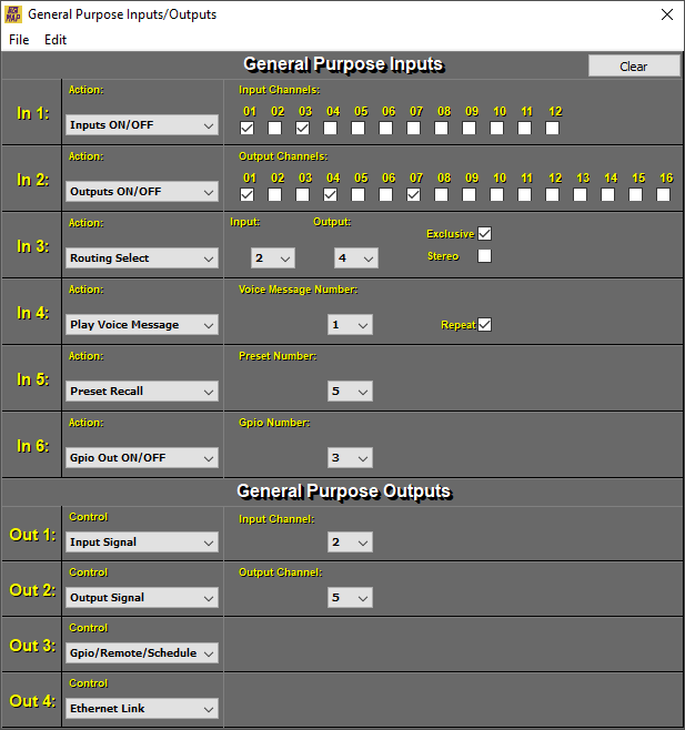
The actions that the GPIO inputs will perform are:
-
Input Level Up/Down: Each transition will produce a 0.5 dB jump up or down on the selected inputs.
-
Inputs ON/OFF: Produces a cyclical change of state between off and on.
-
Inputs ON: Forces the selected inputs to on. It is not cyclical, pressing again does not change the state of the inputs to off.
-
Inputs OFF: Forces the selected inputs to off. It is not cyclical, pressing again does not change the state of the inputs to on.
-
Output Level Up/Down: Each transition will produce a 0.5 dB jump up or down on the selected outputs.
-
Outputs ON/OFF: Produces a cyclical change of state between off and on.
-
Outputs ON: Forces the selected outputs to on. It is not cyclical, pressing again does not change the state of the inputs to off.
-
Outputs OFF: Forces the status of the selected outputs to off. It is not cyclical, pressing again does not change the state of the inputs to on.
-
Routing Level Up/Down: Each transition will produce a 0.5 dB jump up or down in the input signal of the selected routing.
-
Routing Select : Switches the routing inputs on the selected outputs from on (0 dB) to off (-oo) and vice versa. Selecting the Stereo option allows a duo combination. Selecting the Exclusive option only the last selected input will remain active canceling the other routed inputs.
-
Preset Recall: Makes a memory call of the selected Preset within the range 1 to 10.
-
Play Voice Message: Play a Voice Message from 1 to 5. Activating the Repeat option triggers a continuous loop of repetition.
NOTE: See section 7.3.5. Voice Message Panel for additional information.
-
Gpio Out ON: Forces the state of the selected GPIO output to on, logic 1. It is not cyclical.
-
Gpio Out OFF: Forces the state of the selected GPIO output to off, logic 0. It is not cyclical.
-
Gpio Out ON/OFF: It produces a cyclical change of state between off and on, logic 1 or 0 respectively.
The values taken by the GPIO outputs depending on the assigned function are:
-
Input ON/OFF: The GPIO output will reflect the status of the selected input channel (from 1 to 12). When the selected input channel is activated (-ON-), the GPIO output will be active (logic 1, circuit conducting). When this channel is deactivated (-OFF-) the GPIO output will go inactive (logic 0, open circuit).
-
Input Signal : When the input signal reaches the signal presence level (Signal >= -40 dBu) the GPIO output will be active (logic 1, driving circuit) otherwise the GPIO output it will go inactive (logic 0, open circuit).
-
Input Peak: When the input signal reaches the peak level (Signal >= +14.5 dBu) the GPIO output will be active (logic 1, driving circuit) otherwise the GPIO output will go inactive (logic 0, open circuit).
-
Output ON/OFF : The GPIO output will reflect the status of the selected output channel (1 to 8 or 16 depending on the MAP unit you have). When the output channel is activated (-ON-), the GPIO output will be active (logic 1, circuit conducting). When this channel is deactivated (-OFF-) the GPIO output will go inactive (logic 0, open circuit).
-
Output Signal : When the output signal reaches the signal presence level (Signal >= -40 dBu) the GPIO output will be active (logic 1, driving circuit) otherwise the GPIO output it will go inactive (logic 0, open circuit).
-
Output Peak : When the output signal reaches the peak level (Signal >= +14.5 dBu) the GPIO output will be active (logic 1, circuit driving) otherwise the GPIO output will go to inactive (logic 0, open circuit).
-
Gpio/Remote/Scheduled Tasks: The GPIO output will reflect the status or action of a remote key (REM-2) pressed or the start of a scheduled task. This specification is very useful for remote opening of curtains or LCD screens or for programming lights on and off, among others.
-
Ethernet link: The GPIO output will be activated when the MAP is connected to an Ethernet connection network.
-
USB link: The GPIO output will be activated when the MAP is connected via USB.