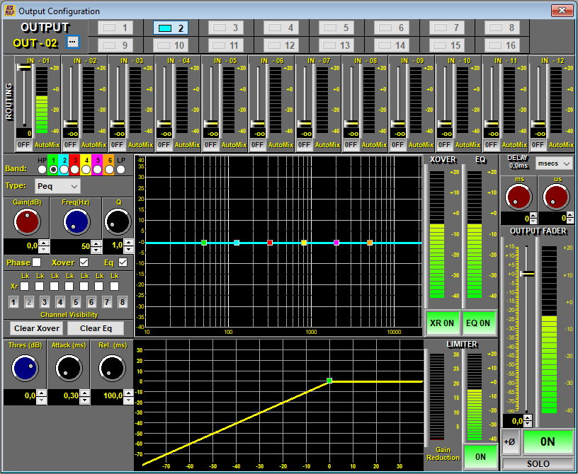
This is the main panel for the control and configuration of each output of the Matrix individually and in more detail.
All available controls are listed below with a brief explanation:
-
Output name: Select the ... button to customize the name of the selected output (It will have a maximum of 8 characters). Example: LIVING ROOM, TERRACE1, etc.
-
Buttons 1 to 8 (MAP128) or 1 to 16 (MAP1216): Output selection keys. Pressing one of these keys will show all the configured parameters of the selected output.
Matrix Section
-
Routing: This panel shows the composition of each output as a mix of inputs. The level of each input can be adjusted from -oo (muted) to 0 dB (maximum), going through all the levels in between.
Each output will therefore correspond to a mix of input signals. If for example in output 1 we are going to use a mono speaker, we will set inputs 1 and 2 to the maximum (in this example L and R of a CD). The fact of being able to adjust levels allows partial adjustments or adjustments of background music on a main signal or a microphone.
-
Output Fader: Represented with an extra detailed level indicator. These elements can be defined with certain movements of the Fader:
-
DOUBLE CLICK: Pone el valor del Fader a 0 dB rápidamente.
-
SELECTION: By clicking on the Fader you will select it and it will change from YELLOW to BLUE. From now on you can use the mouse wheel to adjust the level of the selected Fader in 0.5 dB steps.
-
NUMERICAL ADJUSTMENT: You can adjust the Fader value more precisely using the text box located immediately below the level bar (-level bargraph-) of the Fader. This modification can be done using the +/- arrows, the numeric keyboard and the mouse wheel.
-
-
Bargraph: Level indication in dBu from -40 to +20 dB with 4 dB per step. The bar changes color from -green- to -red- and colors in between depending on the level. The indication is twofold: indication of average value by continuous bar and of peak value by single point.
-
Automix: Select the inputs that we want to manage with the Automix system. The inputs that are not included will work in manual mode, that is, they will not be affected by the automatic control. Para más información consulte el apartado 7.2.4.4. Output Automix.
Selecting the Automix mode displays an additional level bar showing the gain reduction activity on that input.
The Automix system generates a lot of processing workload for the DSP so this should be taken into account when optimizing processor resources. See section WORKING LOAD at point 7.1. Installation.
The Automix element works on the configured inputs of a given output. This means that an input can be assigned to operate as Automix for output #1 but at the same time it can be working in manual mode (not assigned in Automix) in the #2 output.
Crossover Section
It is possible to configure a pair of filters HP (-highpass-) and LP (-lowpass-) on each output. By default the outputs are configured without filters or FR (-full range-). The characteristic of the available filters are: Full Range, Butterworth, Bessel and Linkwith-Rilley. Select the full range type if you want to override one of the sections, that is, when filtering is not required. The type of filters as well as the selected slope will depend on the type of speaker, its components, number of channels, etc. Check with their manufacturer.
After choosing the filter type and slope, adjust the frequency manually or graphically on the curve by clicking and hovering over the LP and HP symbols.
-
Checkbox Phase: This button opens or closes the display of the corresponding Phase. They do not affect the outputs.
-
Checkbox Xover: This button opens or closes the corresponding crossover display. They do not affect the outputs.
-
Checkbox Eq: This button opens or closes the corresponding equalizer display. They do not affect the outputs.
-
Checkboxes Lk-Xr: They allow linking the frequency settings of an output with the neighboring output. The type of filter and its slope will be normalized to the previously adjusted cut-off point. The linking is done between an HP filter and another LP with contiguous outputs.
-
Channel Visibility Buttons: They allow the simultaneous visualization of the selected outputs.
-
XR ON/OFF: Activation key of the crossover section. When going to by-pass the filters are deactivated by passing both the high pass and low pass sections to full range. The program asks for confirmation to inform of the importance of this change.
NOTE: It is necessary to carefully observe the selected frequencies as well as their setting in by-pass since most transducers do not support working outside the design bands even for a few seconds. The HP cutoff frequency is the most critical setting on high-frequency drivers. The lower the cutting frequency there is a greater risk of breakage. Typical setting 3 Khz.
-
6 Band EQ: The EQ section consists of a six-band parametric equalizer. Each band can be defined as:
-
Peq: Parametric filter with selectable gain (dB), Frequency (Hz) and bandwidth (Q factor).
-
Low Sh/High Sh: Butterworth type Bass or Treble side filters.
-
Notch: Notch filter. Allows you to cancel a very narrow band without its effect being almost noticeable.
-
-
EQ Graph: Resulting graph of EQ. This can be molded with the mouse or edited numerically:
-
Level/Frequency: They can be edited by sliding up or down (dB) and moving left or right (Frequency).
-
Bandwidth (Q): It can be varied using the mouse wheel positioned over the band identifier.
-
Botón de Banda: To select a Band.
-
Phase Button: It allows to indicate the phase graph.
-
Delete Clear: Allows you to reset the EQ to its default settings.
-
-
EQ ON/OFF: EQ on/off or -By-Pass- button. Disconnect the EQ leaving the section semi-transparent to allow for quick activation.
-
EQ parameters can be saved or copied to facilitate adjustment of multiple channels that require the same or similar EQ setting. Use the right mouse button for these options.
Limiter Section
-
Limiter: These limiters are located after the Fader (-Post-Fader-) allowing a final and precise control of the individual level of each MAP output to protect speakers or signals sent to other systems.
-
Threshold: Threshold point or reference level of the limiter trigger. Signals above this reference will be attenuated to the reference level. The threshold can also be adjusted graphically.
-
Attack : Here you can modify the time constant of the Attack limiter (-Atack-) or the time it takes to react.
-
Release: Here you can modify the time constant of the Release limiter (-Release-) or continuation of the effect once the signal has disappeared above the threshold.
Gain Reduction : The magnitude of the eliminated signal in dB is shown in a level bar (-bargraph-).
Delay Section
-
Delay: This component introduces a delay of the output signal that is very useful for various applications, among others to perform a precise phase adjustment by the -time alignment- between transducers. The adjustment range is from 0 (no delay, default value) to 300 ms maximum. The delay can be entered as time or as distance traveled in meters or feet at a given temperature. When the distance is entered the user can define the current temperature and the MAP will adjust the necessary time delay automatically.
Output Fader Section
-
Output Fader: Represented with an extra detailed level indicator. These elements can be defined with certain movements of the Fader:
-
DOUBLE CLICK: Sets the Fader value to 0 dB quickly.
-
SELECTION: When you click on the Fader you will select it and it will change from YELLOW to BLUE. From now on you can use the mouse wheel to adjust the level of the selected Fader in 0.5 dB steps.
-
NUMERICAL ADJUSTMENT: You will be able to adjust the Fader value more precisely using the text box located in the position immediately below the level bar (-level bargraph-) of the Fader . This modification can be done using the +/- arrows, the numeric keyboard and the mouse wheel.
-
-
ON-OFF: Power switch or MUTE of the output. It is activated and displayed indistinctly from both the Outputs and Output Configuration panels.
-
SOLO: This button causes a -solo- of the selected output, mute (turning off) the rest of the outputs. This function is used to isolate an output from the rest of the system so that the system can be analyzed in a check-up procedure. When the MAP is used as a multizone processor, this key will allow a wiring check or quick identification of a subwoofer, individual equalization of its zone, etc. This key should only be used for testing, it will NEVER be used in daily processing. Pressing this button again will return the system to its previous state without the need to reposition any faders.
NOTE: Use this button with caution.
-
Phase: Changes the relative phase of the output signal. Useful for aligning subwoofer cabinets or temporarily compensating for phase reversed wiring.