→ Configuration → Remote Controls
NOTE: See section 6.3. Remote Control for additional information.
Up to 32 REM-2 remote controls can be daisy-chained.
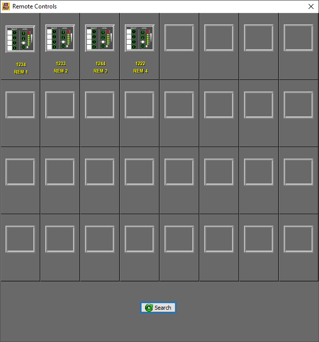
The first window shows a graphic list of all the remotes recognized by the MAP showing the name assigned during the installation, their serial number and numbered from 0 to 31. These data are stored in the remote itself, so it should be taken into account if a replacement is required.
In the event that the remote has been connected after the start of MAP or for maintenance tasks, you can, at any time, select the Search button to find all the remotes that are active in the remote network. Select the remote you want to configure to enter the properties window of that remote.
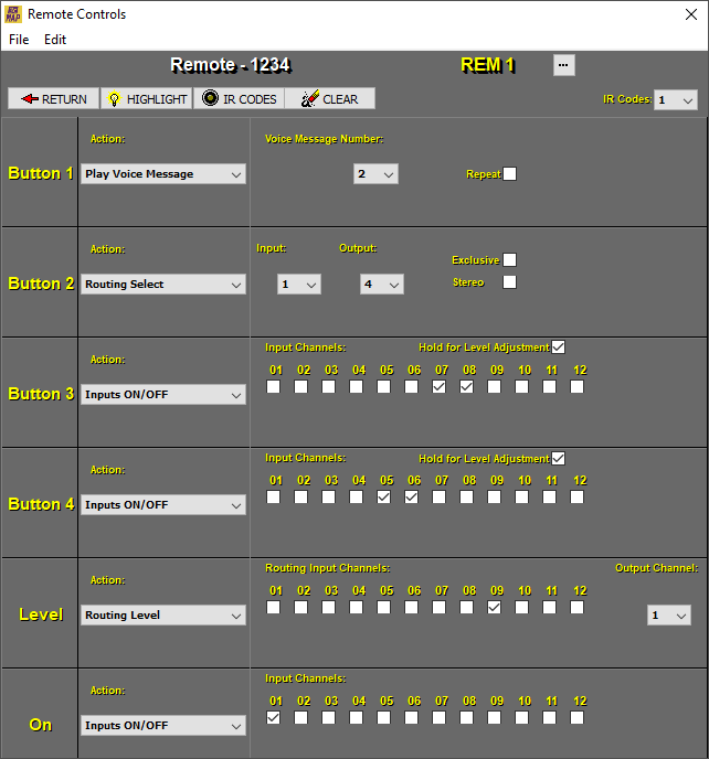
The following elements will be displayed in the properties window:
-
File: Load or Save the configuration files of the Scheduled Tasks.
-
Edit: Copy or Paste configuration options for Scheduled Tasks.
-
Return: Returns to the previous remote selection page.
-
Highlight: It causes the LEDs of the selected remote to blink to help locate it.
-
IR Codes: This screen shows the IR (InfraRed) code assigned to each key. The REM-2 device allows code learning to accommodate a wide variety of remotes.
NOTE: Additional information in 10. REM-2 (Remote Controls).
-
Clear: Resets the name and parameters of the remote to the default values.
-
Button …: Allows you to assign a name to the remote, it is recommended to give it a descriptive name. Example: LIVING ROOM.
-
IR Codes dropdown: Allows you to select a set of infrared codes between 1 and 10. Allows the use of multiple remote controls in the same room. For most installations, assign set #1 that corresponds to the factory codes of the Altair IR-02 infrared remote control.
For each key from Button 1 to Button 4, you can define a Action among the following:
-
Inputs Level Up/Down: Each transition will produce a 0.5 dB jump up or down respectively in the level of the selected inputs.
-
Inputs ON/OFF: It produces a cyclical change in the state of the selected inputs between off and on. (*Setting)
-
Inputs ON: Forces the state of the selected inputs to on. It is not cyclical, pressing again will not change the status of the selected inputs to off. (*Setting)
-
Inputs OFF: Forces the state of the selected inputs to off. It is not cyclical, pressing again will not change the status of the selected inputs to on. (*Setting)
*Setting: In the 3 previous options if we leave the option of Hold for Level Adjustment checked, the remote control will allow a level adjustment of the selected inputs by holding down the corresponding button and adjusting with the +/- keys.
-
Outputs Level Up/Down: Each transition will produce a 0.5 dB jump up or down respectively in the level of the selected outputs.
-
Outputs ON/OFF: Produces a cyclical change in the state of the selected outputs between off and on. (*Setting)
-
Outputs ON: Forces the state of the selected outputs to on. It is not cyclical, pressing again will not change the status of the selected outputs to off. (*Setting)
-
Outputs OFF: Forces the state of the selected outputs to off. It is not cyclical, pressing again will not change the state of the selected outputs to on. (*Setting)
*Setting: In the 3 previous options, if we leave the option of Hold for Level Adjustment checked, the remote control will allow a level adjustment of the selected outputs by holding down the corresponding button and adjusting with the +/- keys.
-
Routing Level Up/Down: Each transition will produce a 0.5 dB jump up or down respectively in signal from the selected routing inputs.
-
Routing Select: Toggle the routing inputs on the selected outputs from on (0 dB) to off (-oo) and vice versa. Selecting the Stereo option allows a duo combination. By selecting the Exclusive option, only the last one selected will remain active, canceling the other routes.
-
Preset Recall: Calls the memory of the selected preset within the range 1 to 10.
-
Play Voice Messages : Plays a Voice Message from 1 to 5. Selecting the Repeat option activates a continuous loop of repetition of said Voice Message.
NOTE: See section 7.3.5. Voice Message Panel for additional information.
-
Gpio Out ON: Forces the state of the selected GPIO output to on, logic 1. It is not cyclical.
-
Gpio Out OFF: Forces the state of the selected GPIO output to off, logic 0. It is not cyclical.
-
Gpio Out ON/OFF: It produces a cyclical change of state in the selected output between off and on, logic 0 and logic 1 respectively.
The LEVEL keys can perform level adjustment functions depending on the function you define:
-
Input Level: Each press of the +/- keys produces a 0.5 dB jump up or down on the selected inputs.
-
Output Level: Each press of the +/- keys produces a 0.5 dB jump up or down on the selected outputs.
-
Routing Level: Each press of the +/- keys causes a 0.5 dB jump to change up or down in the selected routing.
The power key ON can be configured to perform the following Actions:
-
Inputs ON/OFF: It produces a cyclical change in the state of the selected inputs between off and on.
-
Inputs ON: Forces the state of the selected inputs to on. It is not cyclical, pressing again will not change the status of the selected inputs to off.
-
Inputs OFF: Forces the state of the selected inputs to off. It is not cyclical, pressing again will not change the status of the selected inputs to on.
-
Outputs ON/OFF: Produces a cyclical change in the state of the selected outputs between off and on.
-
Outputs ON: Forces the state of the selected outputs to on. It is not cyclical, pressing again will not change the status of the selected outputs to off.
-
Outputs OFF: Forces the state of the selected outputs to off. It is not cyclical, pressing again will not change the state of the selected outputs to on.
-
Gpio Out ON: Forces the state of the selected GPIO output to on, logic 1. It is not cyclical.
-
Gpio Out OFF: Forces the state of the selected GPIO output to off, logic 0. It is not cyclical.
-
Gpio Out ON/OFF: It produces a cyclical change of state in the selected output between off and on, logic 0 and logic 1 respectively.
-
Preset Recall: Makes a memory recall of the selected preset within the range 1 to 10. The remote will light up when loading is done. This will blink when a change is made to the assigned preset.
-
Play Voice Messages: Plays a Voice Message from 1 to 5. Selecting the Repeat option activates a continuous loop of repetition of said Voice Message. Voice.
NOTE: See section 7.3.5. Voice Message Panel for additional information.
KEY ILLUMINATION. 8 POINT LED BAR
All keys are illuminated. When a key is selected as Up/Down it will light up at the end of the setting. When a key is defined as change of state (ON-OFF-ON) the led will indicate the state it is in. When more than one input/output or routing is defined, the top lighting will correspond to the input/output or routing channel that reaches the end of the setting first.
A column of eight LEDs indicates the current value in dBu of the input or output channel defined in the LEVEL adjustment keys. The column of LEDs also serves for a momentary indication of the set point in dB. LEDs 1 through 6 are green and LEDs 7 and 8 are red (region above 0 dB).