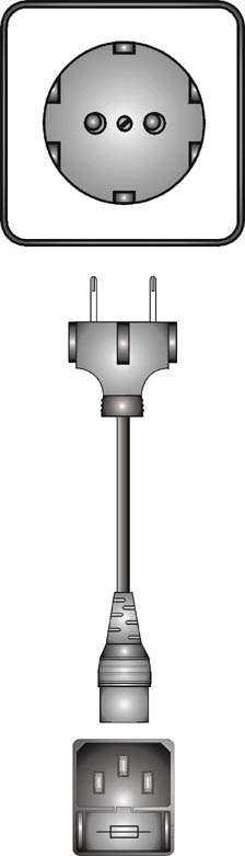
The MAP connection to the network is made using a factory-supplied three-pole cable.
-
Make sure the appliance's power switch is in the 0 (off) position.
-
Insert the female connector of the 3-pole cable into the device's mains connector located on the rear panel.
-
Insert the male connector of the 3-pole cable into the mains socket.
-
Turn on the power switch on the appliance. At that moment all the front panel LEDs will light up in white and a check scan of all the LEDs will be performed, indicating that the unit has been turned on.
-
After the sweep, the LEDs will go on to indicate the required function. The STATUS LED will illuminate green, indicating a correct operation of the unit, in the event that an error occurs at the start-up, said status LED STATUS will light red.
 CAUTION: Always ensure that the mains voltage to which you are going to connect the appliance, as well as its fuse, are correct.
 The processor has a universal power supply, and is prepared to work from 90 to 264 VAC, 50-60Hz.
-
Make sure the device is disconnected from the network.
-
The mains connector and fuse holder are located on the rear panel of the unit. The lower part of this network connector is the so-called fuse box. Remove the fuse holder.
-
When removing the fuse holder, the fuse will appear, if you want to change it take it out and replace it with the new one.
-
Insert the fuse holder back into the network connector.
-
Make sure the fuse is correct: T2A.
CAUTION: Always make sure when changing the fuse that it is the correct one.
Before leaving the factory, each central unit receives an exhaustive quality control, so if when unpacking the unit you notice that it has suffered some damage during transport, do not connect the device to the network, contact the seller so that the unit is inspected by qualified technical personnel.
Keep the original packaging, it can be useful if you need to transport the appliance. NEVER TRANSPORT THE PROCESSOR WITHOUT PROPER PACKAGING.
It is recommended to mount the unit in standard cabinets either for protection, security or even aesthetics. etc. The ALTAIR MAP128 / MAP1216 units are designed for standard 19" rack mounting. occupying a unit of height, 1HE.
If the unit is to be operated in an ambient temperature above 35ºC (100ºF), it is recommended to install the unit leaving a hollow space above and below to allow fresh air to circulate on both sides of the unit. The installation of forced air systems and even cooling systems should be considered according to the criteria of the installer.
Avoid direct exposure to the sun or other intense sources of heat.
The following are the steps to follow for the correct unpacking, installation, change of fuses and connection to the electrical network of your MAP device:
-
4.1. – Unpacking
-
4.2. – Mounting
-
4.3. – Change of the Fuse
-
4.4. – Connection to the Mains