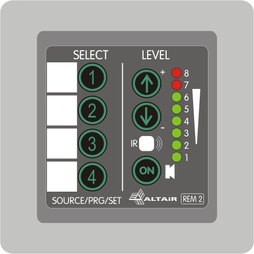
The REM-2 / REM-2R device is a wired remote control intended for use in audio installations equipped with Altair MAP series Audio processors. The remote control includes a group of 4 keys that can be programmed from the Altair 3cMAP software, allowing each key a large number of functions (Actions) such as Recall a Preset, selection of routing, control of outputs and logic inputs (GPIO ), etc.
The panel incorporates a pair of up/down keys (model REM-2) or rotary control (model REM-2R) that can also be defined from the 3cMAP as volume control, parameter scroll, etc. The Mute key allows a momentary shutdown of the selected speakers. An LED bar (-bargraph-) is included, consisting of eight LEDs for instant level indication, volume adjustment of the selected zone or as status indication.
The panel includes an infrared sensor for remote control with the Altair IR-02 remote or any other compatible remote.
Below are detailed concepts about the assembly, power supply and how to use the REM-2:
-
10.1. – REM-2 Installation
-
10.2. – Wiring
-
10.3. – Connection and Powering
-
10.4. – Operation Panel
-
10.5. – Infrared Control
-
10.6. – Firmware Update
-
10.7. – Technical Specifications
The REM-2/REM-2R panel has been designed to install on European boxes of electrical mechanisms, either flush or on surface boxes.
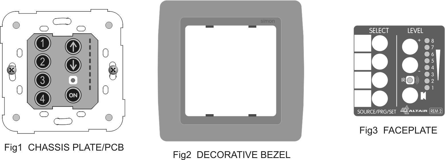
The unit is factory assembled for quality control purposes and should be disassembled and installed following the normal wall fixture mounting process.
DISASSEMBLY: Separate the 3 parts by levering between the metal chassis and the trim using a small screwdriver. If the unit is already installed on the wall, simply pry between the unit and the wall with caution.
The unit is made up of three parts: set -plate/circuit board-, decorative frame and machined panel. Keyed version shown:
Mechanism Box Mounting
-
Install the assembly -frame/circuit board- in the mechanism box using the 2 screws supplied in the mechanism box. The unit can be mounted using two screws in horizontal mounting (as shown) or in a vertical position for convenience. Check that the 4 cables are firmly screwed into the connector.
-
Mount the decorative frame by centering the 4 lugs in the holes in the chassis.
-
Center the machined panel over the pushbuttons as shown. Apply a balanced force on all 4 corners at the same time until you hear a click. Review the 7 key travel. If necessary, disassemble the assembly and try again.
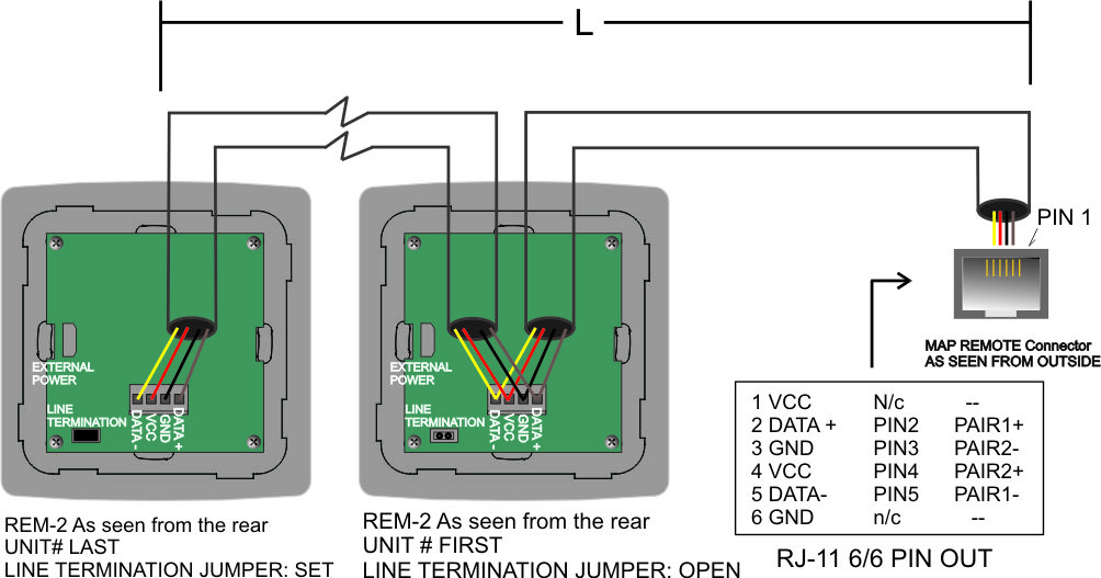
Cabling is done with 2 pairs of cat5 cabling or equivalent (four wires total) as shown in the figure.
Usually 2 pairs are used and the other 2 are left as spare or for another purpose.
The last unit should be finished. Simply close the supplied jumper that by default is placed but open.
Given the losses of the cables, a maximum cable length is established according to the table:
|
Nº OF REMOTES |
MAX CABLE LENGTH [m/(ft)] from first to last |
|---|---|
|
1 |
200/(650) |
|
2 |
100/(325) |
|
3 to 4 |
50/(165) |
|
5 to 8 |
25/(82) |
Cable cat5, 0.2mm2, AWG24
The REM-2/REM-2R remote control must be daisy-chained or star-mounted with the MAP processor. In either case, all remotes will be wired in parallel pin to pin.
The star mounting allows less cumulative copper losses, better control of the installation at a cost of a greater investment in wiring.
The unit incorporates an automatic addressing system so that no local adjustment is necessary. The system will recognize the units one by one identifying and naming in the remote control network.
The installation can be carried out in various ways depending on the number of remotes or the length of the installation wiring. Below are several recommended mounts depending on the size of the installation:
-
10.2.1. – Small Installations
-
10.2.2. – Medium Installations
-
10.2.3. – Large Installations
NOTE: We recommend using flexible wire cabling. Avoid rigid conductor cables.
Cabling is done with 3 pairs of cat5 or equivalent cabling (six wires total) as shown in the figure.
The last unit should be finished. Simply close the supplied jumper that by default is placed but open.
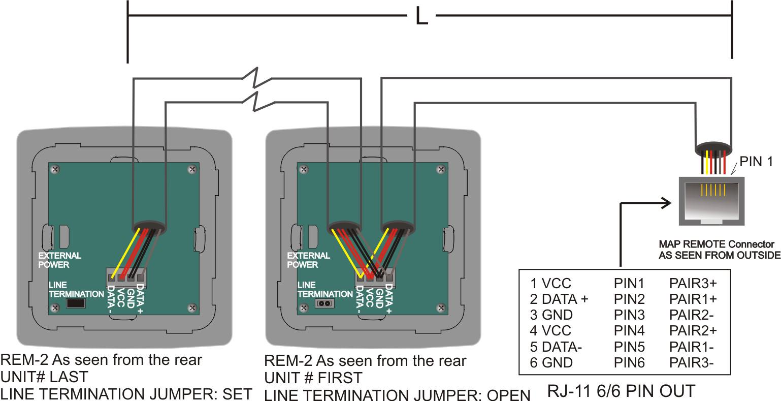
Given the losses of the cables, a maximum cable length is established according to the table:
|
Nº OF REMOTES |
MAX CABLE LENGTH [m/(ft)] from first to last |
|---|---|
|
1 |
400/(1300) |
|
2 |
200/(650) |
|
3 to 4 |
100/(325) |
|
5 to 8 |
50/(165) |
Cable cat5, 0.2mm2, AWG24